Lets try to know LCD Interface.

Liquid Crystal Display (LCD) consists of rod-shaped tiny molecules sandwiched between a flat piece of glass and an opaque substrate. These rod-shaped molecules in between the plates align into two different physical positions based on the electric charge applied to them. When electric charge is applied they align to block the light entering through them, where as when no-charge is applied they become transparent.
Light passing through makes the desired images appear. This is the basic concept behind LCD displays.
LCDs are most commonly used because of their advantages over other display technologies. They are thin and flat and consume very small amount of power compared to LED displays and cathode ray tubes (CRTs).
►Pin Description
The most commonly used LCDs found in the market today are 1 Line, 2 Line or 4 Line LCDs which have only 1 controller and support at most of 80 charachers, whereas LCDs supporting more than 80 characters make use of 2 HD44780 controllers.
Most LCDs with 1 controller has 14 Pins and LCDs with 2 controller has 16 Pins (two pins are extra in both for back-light LED connections). Pin description is shown in the table below.
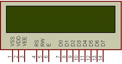 Figure 1: Character LCD type HD44780 Pin diagram
| Pin No. | Name | Description |
| Pin no. 1 | VSS | Power supply (GND) |
| Pin no. 2 | VCC | Power supply (+5V) |
| Pin no. 3 | VEE | Contrast adjust |
| Pin no. 4 | RS | 0 = Instruction input 1 = Data input |
| Pin no. 5 | R/W | 0 = Write to LCD module 1 = Read from LCD module |
| Pin no. 6 | EN | Enable signal |
| Pin no. 7 | D0 | Data bus line 0 (LSB) |
| Pin no. 8 | D1 | Data bus line 1 |
| Pin no. 9 | D2 | Data bus line 2 |
| Pin no. 10 | D3 | Data bus line 3 |
| Pin no. 11 | D4 | Data bus line 4 |
| Pin no. 12 | D5 | Data bus line 5 |
| Pin no. 13 | D6 | Data bus line 6 |
| Pin no. 14 | D7 | Data bus line 7 (MSB) |
| Pin No. | Name | Description |
| Pin no. 1 | D7 | Data bus line 7 (MSB) |
| Pin no. 2 | D6 | Data bus line 6 |
| Pin no. 3 | D5 | Data bus line 5 |
| Pin no. 4 | D4 | Data bus line 4 |
| Pin no. 5 | D3 | Data bus line 3 |
| Pin no. 6 | D2 | Data bus line 2 |
| Pin no. 7 | D1 | Data bus line 1 |
| Pin no. 8 | D0 | Data bus line 0 (LSB) |
| Pin no. 9 | EN1 | Enable signal for row 0 and 1 (1stcontroller) |
| Pin no. 10 | R/W | 0 = Write to LCD module 1 = Read from LCD module |
| Pin no. 11 | RS | 0 = Instruction input 1 = Data input |
| Pin no. 12 | VEE | Contrast adjust |
| Pin no. 13 | VSS | Power supply (GND) |
| Pin no. 14 | VCC | Power supply (+5V) |
| Pin no. 15 | EN2 | Enable signal for row 2 and 3 (2ndcontroller) |
| Pin no. 16 | NC | Not Connected |


0 comments:
Post a Comment